top of page
CINDY SU'S PORTFOLIO

EK 131: ROOM TEMPERATURE MONITOR
For my EK131 Introduction to Engineering class, we were instructed to create a room temperature monitor. This monitor was created through a variety of manufacturing methods including 3-D printing, soldering, laser engraving, and hole drilling. Besides assembling a number of mechanical and electrical components, a code was programmed to an arduino to read and record the room temperature, notifying the user if it the temperature is out of a given range.
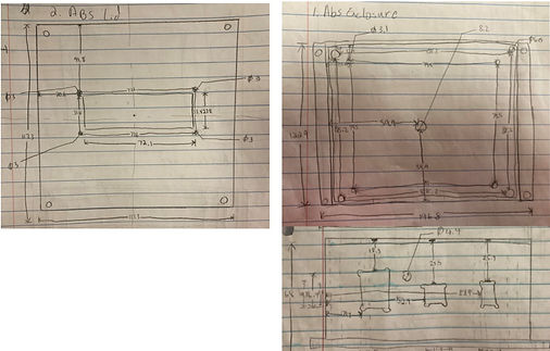
Before assembling the project, I used digital calipers to take measurements of all the components. After taking the measurements, I drew mechanical drawings, which also included the measurements.

Figure 1: Mechanical Drawings of the ABS enclosure and lid
Next, I needed to gather all the components for the project.
This included:
-
An ABS enclosure
-
Mounting Plate
-
Screws
-
Spacers
-
22 AWG male to female jumper wires
-
LCD screen
-
Buzzer
-
Red LED
-
Green LED
-
Temperature sensor (TMP36)
-
Arduino
-
9V battery
-
9V battery snap
-
Resistors
-
USB cable
-
Switch
-
Connectors
-
Soldering wire
-
Heat tubing
-
3-D printed battery holder
While gathering the materials, there were a couple of conditions I had to fulfill in order for the project to work. The first consideration was selecting the wire gauge. According to the amplicity table provided by my class, the maximum current that the 22 AWG wires could handle was 920 mA and the maximum current that is drawn in the circuit used for the project would be less than 100 mA. By selecting an AWG of 22, this would mean that the wires would be able to handle the amount of current contained in the circuit.
Another factor to keep in mind was selecting the voltage of the battery. The purpose of the battery was to help power the arduino, which accepts voltages in the range 6-20 V. Since the 9V battery fell into that range, it was a perfect candidate.
Finally, the placement of my components were determined to ensure that there was enough room. All the components were ultimately placed inside the ABS enclosure. When it comes to the placement location of the electric/electronic components, the arduino and the battery were both placed inside of the enclosure, which made it easy and accessible for the arduino to be powered by the battery holder. In addition, the green LED, red LED, buzzer, temperature sensor, switch, and parts of the arduino were protruded through the holes that were drilled into the enclosure. This allowed the user to be able to detect whether the device was turned on and whether or not the temperature was out of range without opening the box.
As for the temperature sensor, by allowing it to protrude out the box, it allows for a more accurate reading of the room temperature. Finally, by allowing parts of the arduino to be protruded, it made it easy to plug it into the computer so that it can be programmed. The wires are also placed in the box so that they may not interfere with other substances that can make it volatile such as water. Moreover, the LCD screen was placed on top of the lid so that the temperature could be easily read without opening the box.
After taking these considerations, I 3-D printed a battery holder. This was designed through Onshape and then printed through a software called Ultimaker Cura.
Now, it was time to assemble.
Starting with the mechanical components, I used screws and spacers to attach the mounting plate to the ABS enclosure. After that I used a drill press and a drill to create holes in the enclosure for the protruded components. Later, I used a hot glue gun to glue the battery holder on the mounting plate.
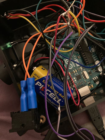
Next was the soldering. Using a multitude of wires, I soldered the components and wires together, securing them with heat tubing and connectors. Unfortunately, there were times where I accidentally soldered the wrong wires together. As a result, I had to cut the wires apart and re-solder the wires with a new one.
Finally, after soldering everything together, I had to program to arduino code. There are a couple things to note here. First of all, in order for the code to work, I had to include the LiquidCrystal library. Next, I had to include the dimensions of the LCD screen during the third line of my code. Otherwise, my LCD screen wouldn't have followed the commands of the arduino. Furthermore, when it came to programming the temperature sensing, I had to ensure that the right unit of temperature was read, which was done through a conversion. I also selected a temperature range for the temperature sensor to notify the user if the room temperature was out of that given range.
After putting everything together, I still ran through a couple of issues. First of all, while my program had worked previously, at one point, the code did not work and my LCD displayed nothing. As a result, I had to look over my code again and identify what was preventing it from working. After scouring for a bit, I realized that I accidentally used an older code that I had written, which included incorrect dimensions of the LCD. After modifying it, everything was working again. Shortly after, I realized the temperature sensor had an inaccurate reading of the room temperature, claiming it was in the 90s while the season was merely an early spring. My TA (Teaching Assistant) suggested I look at the 9V battery since it could've been losing voltage. After swapping out my existing battery and testing out several batteries, eventually I found one that worked. Success!
To understand how the components of the assembly functioned together, the temperature sensor can be turned on using a switch and was powered by a battery and an arduino -- which was programmed with a code. While turned on, the green LED would light up while the temperature sensor would detect the room temperature. The temperature detected would be displayed using an LCD screen, in both degrees Fahrenheit and Celsius. In addition, if the temperature sensed was out of range, the red LED would start blinking and a buzzer would start ringing, notifying the user.
Besides dipping my toes into different manufacturing methods, I learned the importance of paying attention to small details. As mentioned before, I made several careless mistakes such as soldering the wrong wires together and accidentally programming the wrong code. It's important that I check everything beforehand so that I don't make any irreversible mistakes. In addition, while my battery holder fit into my enclosure, it was a bit too big and didn't provide enough support. In the future, I definitely need to be more precise with measuring out my designs.

Figure 2: CAD Assembly of Components

Figure 3: Wiring the components (no heat tubes have been added yet!)
bottom of page