CINDY SU'S PORTFOLIO

BURPG: COLD GAS THRUSTER
During my sophomore year, I decided to join the Boston University Rocket Propulsion Group. To get started, I had to create a cold gas thruster.
This was done with several given values:
-
Pressure of atmosphere at sea-level = 14.7 psia
-
Optimal pressure at 45,000 feet = 2.1 psia
-
Room temperature: 293 K (20C)
-
Smallest allowable nozzle diameter: 0.30 in
-
Maximum system chamber pressure: 90 psia
-
Factor of Safety Yield: 2
-
Factor of Safety Ultimate: 3
Now going into this project, I knew almost nothing about how rocketry works except for maybe what a rocket was. To prepare, I had to read over a portion of a rocketry textbook. The project was divided into multiple phases: Conceptual Design, Preliminary Design, and Critical Design. In the Conceptual Design phase, my partner and I had to perform a number of fluid mechanics/thermodynamic calculations to verify that the values we were using went according to theory and to get a sense of what dimensions we'd be using for our thruster design.
This part was difficult because like I said before, I wasn’t very familiar with the material. As a result, this process involved a lot of flipping back and forth in the textbook and going to office hours for help. Eventually we were able to acquire our values.
During the preliminary design, we had to CAD design our thruster via Solidworks and then perform Finite Element Analysis on it using Solidworks Simulation using the given metrics. At this point, my partner for the project had dropped out so managing my time wisely was a big priority of mine.
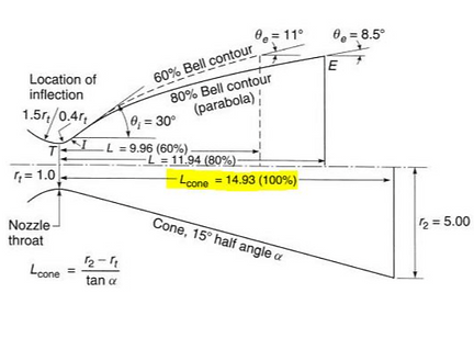
Before designing the nozzle on CAD, I had to determine the type of nozzle shape which would help me determine the dimensions used for the CAD model. I went with the cone nozzle since it had a smaller nozzle divergence angle, which would produce a higher specific impulse. With that determined, I was able to use my nozzle throat and exit diameters to calculate the rest of the dimensions.
Next, it was time to design on Solidworks. I first designed the nozzle using tools such as revolve sketch and cut. After that, since the nozzle was to be fitted on a thruster block, I designed a seal that would fit exactly on the block. I then assembled the nozzle and seal together.
When it came to the FEA aspect, I applied 90 psi to the the throat and exit of the nozzle since it was the maximum system chamber pressure. After that, I added fixtures to all the holes on the seal and then ran the simulation to determine maximum stress.
To determine factor safety, I had to select the material I would be using and find its ultimate and yield strength. I chose abs plastic which meant my yield strength was 6.5 MPa and ultimate strength was 7.37 MPa (found through a google search). Through this and the given FOS values, my thruster needed to have a maximum stress of less than 942.75 psi.
When running through the Simulation, there would be times where the maximum stress of my thruster would exceed the calculated value. I found that by increasing the thickness of my thruster, I was able to decrease the maximum stress to obtain my desired value.
Finally, there was the Critical Design phase which involved selecting material and creating a manufacturing plan. As mentioned previously, I chose abs plastic as my material since it was strong but lightweight and was easy to obtain. For my manufacturing plan, I decided to 3D print at EPIC (Engineering Product and Innovation Center) since it was convenient while providing accurate results.
After my design was approved, in order to prepare for my print, I had to adjust my design with a tolerance of ±0.50mm to ensure that my thruster could fit on the thrust block.
Next, I submitted my printer request and received my part…which came disassembled.
I later realized I had to check something that would allow the assembly to be printed as one instead of printing individual components. A minor mistake, but it resulted in a reprinting of parts.
After my second reprint, I was able to acquire my final product.
Lessons learned:
This project taught me the ins and outs of basic rocket nozzle design using a cold gas thruster. I learned about the various equations used, the specific parameters of nozzle design, calculating factor of safety using Solidworks simulation, and what not to do when 3D printing. Beyond that, I learned how to learn independently. While I went to office hours frequently to seek help, I also spent a lot of time by myself performing online research to find the answer to whatever problem I was stuck on at that moment. Although it was tedious at first, learning independently proved to be very valuable and allowed me to take the time to understand difficult concepts through a variety of sources. I hope to continue to learn more about rocket design in the future.


